
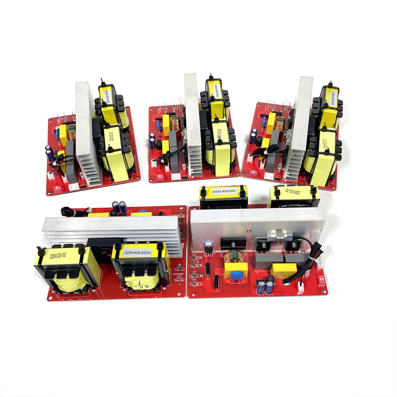

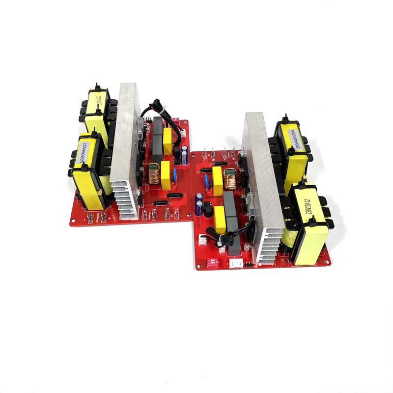
600W-1200W Ultrasonic PCB Generator Driver Ultrasonic Cleaning Transducer PCB Circuit With Digital Panel
The 28KHZ/40KHZ 400W ultrasonic circuit board completes two functions: power amplification and load matching, that is, power amplification amplifies the control signal; Load matching is achieved by using transformers and inductors connected to the input end of the transducer, which can improve the energy transmission…

The 28KHZ/40KHZ 400W ultrasonic circuit board completes two functions: power amplification and load matching, that is, power amplification amplifies the control signal; Load matching is achieved by using transformers and inductors connected to the input end of the transducer, which can improve the energy transmission efficiency between the driving circuit and the transducer, enabling the transducer to obtain sufficient power. At the same time, the matching circuit can also be used for filtering, converting square waves into sine waves, and reducing high-frequency harmonics. The external transformer further boosts the voltage, enabling the ultrasonic motor to operate normally.
The 28KHZ/40KHZ 400W ultrasonic circuit board cannot meet all filtering requirements due to the fact that the sine wave output by the driving circuit is obtained through matching circuit filtering, and different ultrasonic motors have a large operating frequency range. Therefore, the universality of using switch inverter drive circuits is relatively low.
28KHZ/40KHZ 400W ultrasonic circuit board is a frequency synthesis technology that directly synthesizes the required waveform based on the phase concept, which can easily generate sine signals with adjustable frequency, phase, and amplitude. Using the sampling theorem, generate waveforms through table lookup. Figure 2 shows the basic circuit principle of DDs. The output of the phase accumulator is the phase of the synthesized signal. The digital waveform stored in the digital table is extracted using the lookup table method, and the analog waveform is formed through the D/A converter. The stepped wave output by D/A.
| Type | Power(W) | Frequency (KHz) |
| PU-PCB200W | 200 | 20khz,25khz,28khz,33khz,40khz Frequency is adjustable 50khz,54khz,60khz,68khz,80khz,90khz 100khz,120khz,135khz,165khz,200khz |
| PU-PCB300W | 300 | 20khz,25khz,28khz,33khz,40khz Frequency is adjustable 50khz,54khz,60khz,68khz,80khz,90khz 100khz,120khz,135khz |
| PU-PCB400W | 400 | 20khz,25khz,28khz,33khz,40khz Frequency is adjustable |
| PU-PCB500W | 500 | 20khz,25khz,28khz,33khz,40khz Frequency is adjustable |
| PU-PCB600W | 600 | 20khz,25khz,28khz,33khz,40khz Frequency is adjustable |
标签:600W-1200W Ultrasonic PCB Generator Driver Ultrasonic Cleaning Transducer PCB Circuit
Send Inquiry
 28KHZ 2000W Digital Ultrasonic Frequency Generator PCB For Industrial Ultrasonic Cleaner/Dishwasher
 400W Ultrasonic Sound Generator Electronic Control Board Ultrasonic Power Supply Pcb Generator Circuit Board Pcb Generator
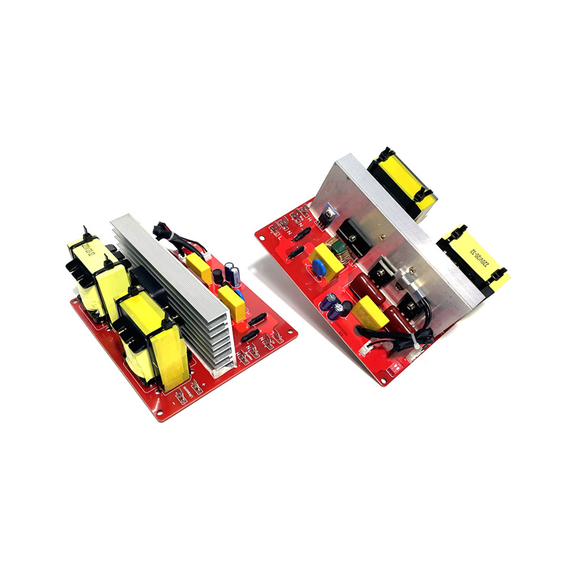 300W-600W Ultrasonic PCB Generator Power Supply For Medical Car Engine Metal Parts Cleaner
 Motherboard PCB Ultrasonic Generator With Timer Adjuster Ultrasonic Generator Cleaning Board PCB Motherboard
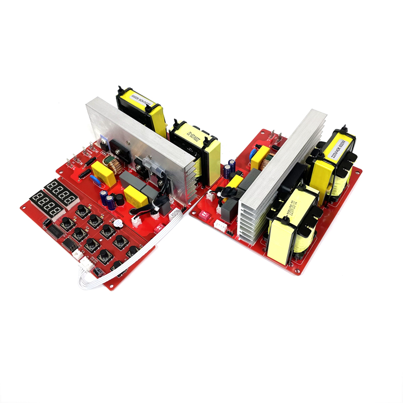 28KHZ-40KHZ 2400W Ultrasound Cleaner Generator PCB For Ultrasonic Submersible Immersible Transducer Pack
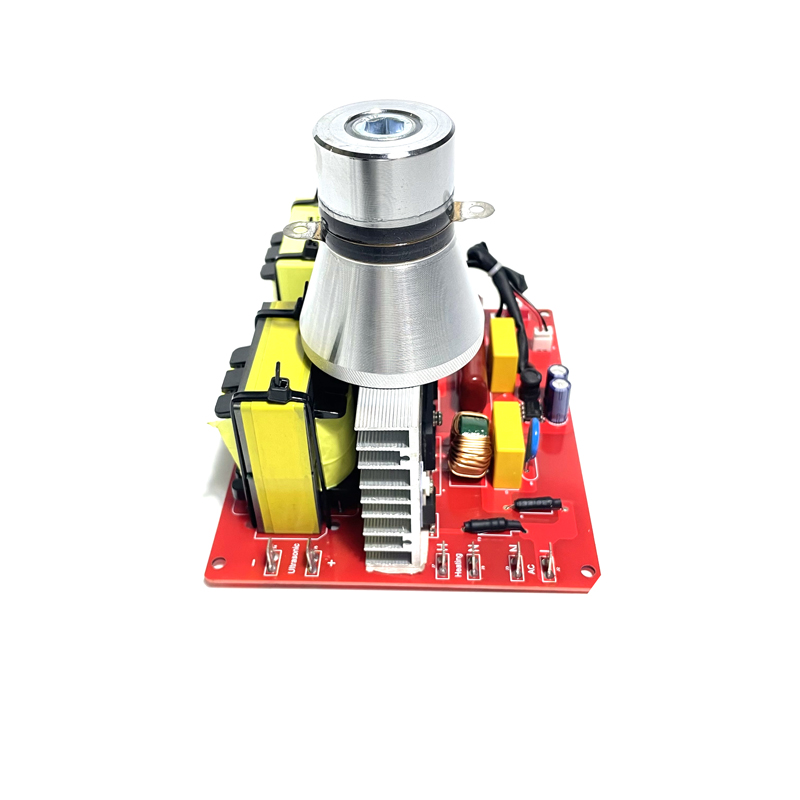 Ultrasonic High Power Signal 200W Ultrasonic Generator 25khz PCB For Driving Transducer Cleaning
 Ultrasonic Pcb Control Board 40kHz Ultrasonic Generator PCB Board Driver Circuit Power Supply For Ultrasonic Cleaner
 Cleaner Machine Sound Generator Circuit Sweep Frequency Ultrasonic Generator PCB Auto Frequency Tracking Circuit PCB
 Ultrasonic Cleaner Pcb Printed Circuit Board Piezo Ultrasonic Transducer Driver Circuit PCB Board Generator
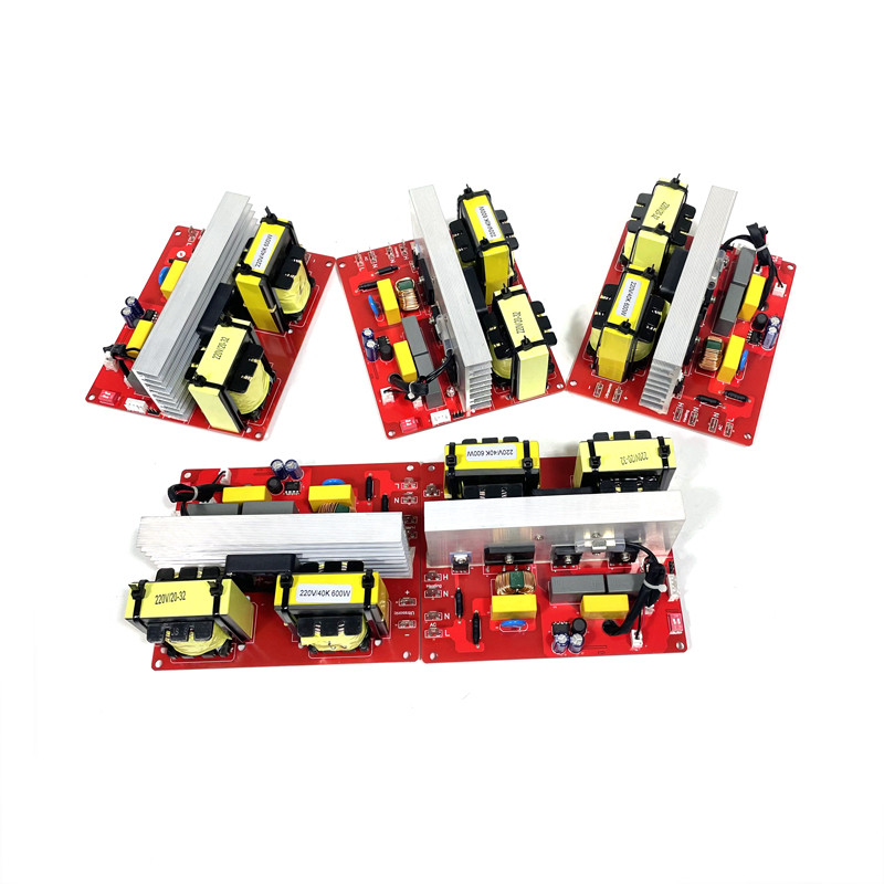 3000W Ultrasonic Generator PCB Power Supply Ultrasonic Transducer Driver Circuit For Industrial Cleaning System
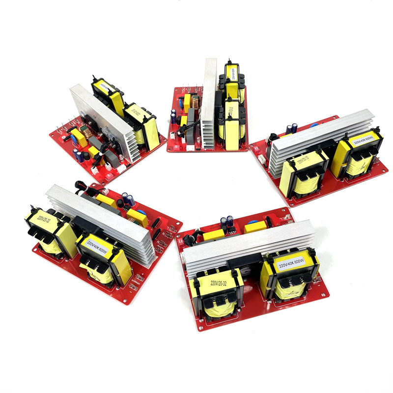 Ultrasonic PCB Circuit Motherboard 40KHZ 300W Ultrasonic Generator Kit Circuit PCB Board Piezo Transducer Driver Circuit
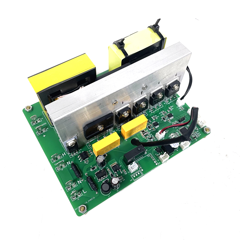 600W 110V-220V Pcb Board Ultrasonic Circuit Generator Degas Sweep Display Board Control Ultrasonic Generator Pcb